The calculation method follows 3 steps:
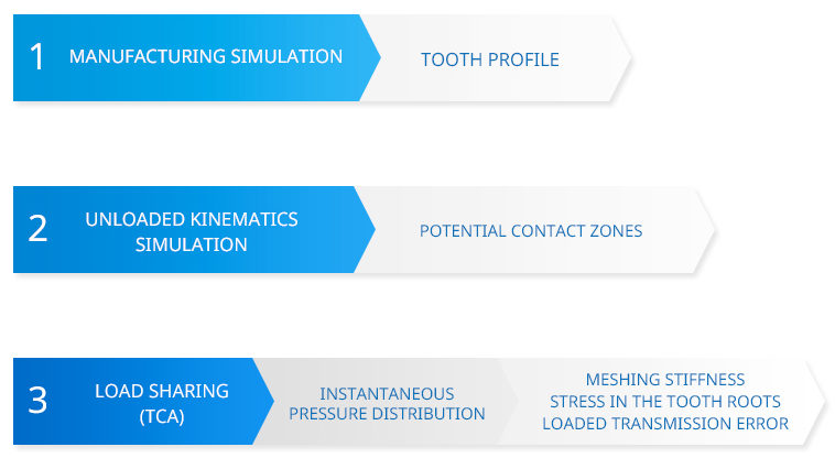
1– Tooth profile definition
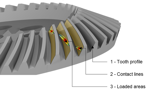
The tooth profiles are obtained by analytical formulas or accurate simulation of the manufacturing process. Tooth modifications may be considered, as well as manufacturing defaults.
CAD gear parts are automatically generated and can be used directly in a definition drawing, or to achieve CAM or FE computations.
2 – Unloaded kinematics
Knowing the tooth profiles, the simulation of the unloaded kinematic is carried out to obtain the potential contact zones or the unloaded kinematics error.
Misalignments can be taken into account.
3 – Load sharing
The load sharing is achieved on the potential contact zones. Deformations due to contact and bending of the teeth and their surroundings are taken into account. The model is solved by the displacement compatibility equations, using the influence coefficients method.
Contact deformations are calculated by the Boussinesq formulations.
The bending displacements are obtained by combining:
- A single finite element computation, taking into account the surroundings of the gear (shafts, rims, web, bearing positions and stiffness …)
- and sets of interpolation functions to accelerate the computing time
The load sharing allows for example to obtain the instantaneous pressures distribution, transmission error, meshing stiffness, flash temperature, tooth root stresses, backlash…